DevicesPV hybrid and battery inverters
Supported Devices
| Device Type | Variants | Modbus TCP (Ethernet) | RS485 | Curtailment |
|---|---|---|---|---|
| Single Phase LV Hybrid Inverters (SG0XLP1-EU) | SUN-3/3.6/5/6/7/7.6/8/10/12K | ❌ | ✅ | ❌ |
| Three Phase LV Hybrid Inverters (SG0XLP3-EU) | SUN-3/4/5/6/8/10/12/14/15/16/18/20K | |||
| Three Phase HV Hybrid Inverters (SG0XHP3-EU) | SUN-5/6/8/10/12/15/20/25/29.9/30/35/40/50/60/70/75/80K | |||
| Single Phase String Inverters (G0XP1-EU) | SUN-1/1.5/2/2.2/2.5/2.7/3/3.3/3.6/4/4.2/4.6/5/5.2/6/6.2/7/7.5/8/9/10/10.5K | |||
| Three Phase String Inverters (G0XP3-EU) | SUN-3/4/5/6/7/8/9/10/12/15/18/20/22/23/25/30/35/36/40/45/50/60/70/75/80/90/100/120/125/130/135/136K |
Wiring
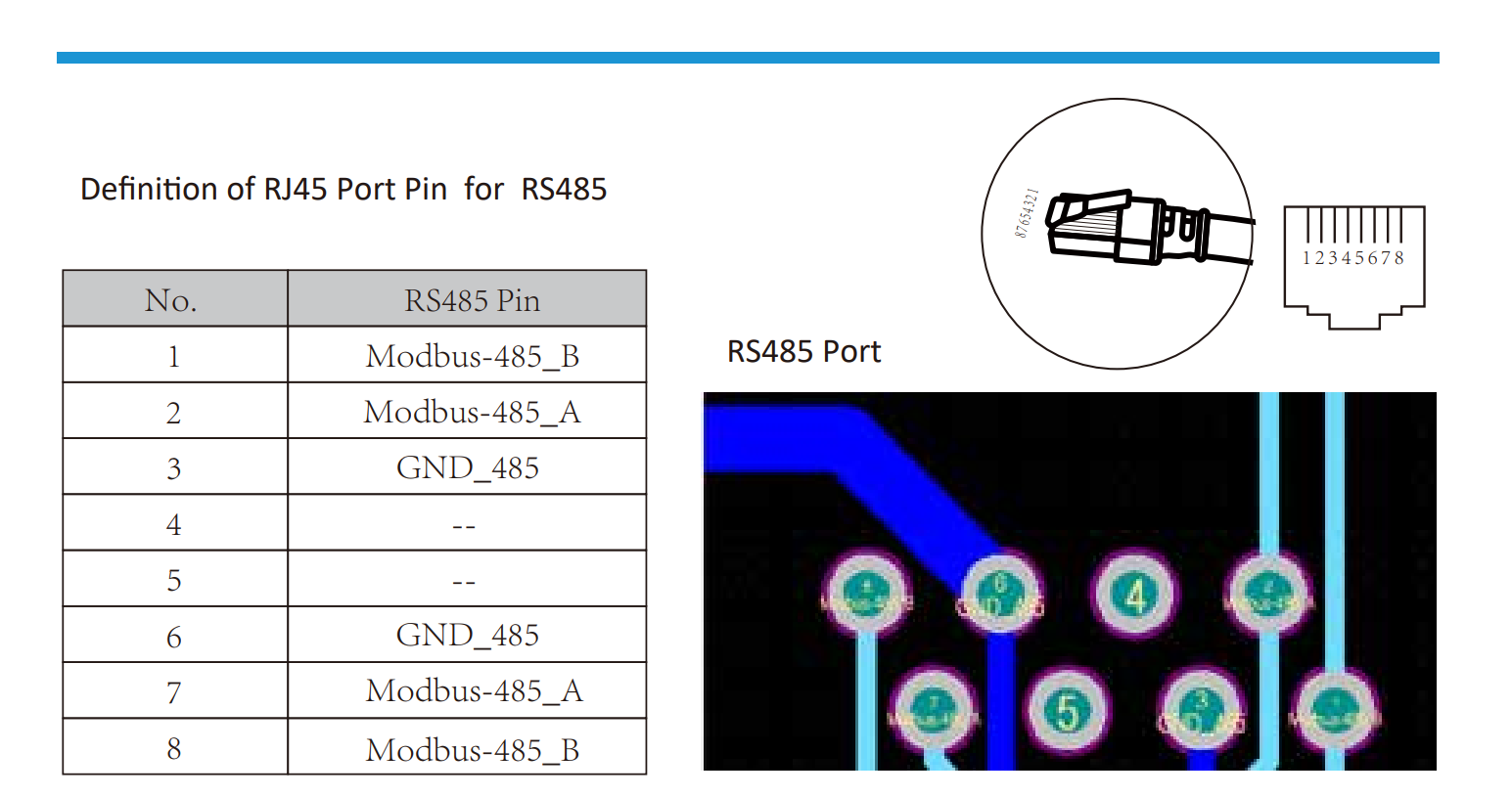
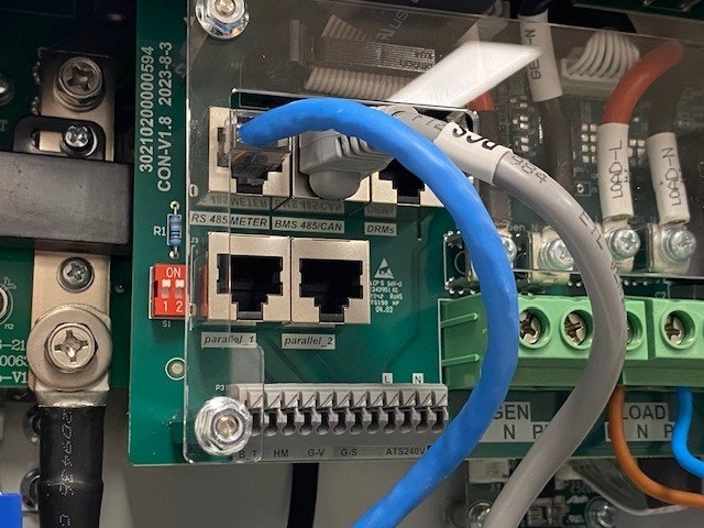
RS485
RS485 Wiring
- For correct RS485 wiring: Follow the guidelines for RS485 wiring.
- If the wiring shown in the table below is incorrect, please let us know.
- There is no general consensus in the industry about the usage of A and B for the RS485 polarity, so it may be counterintuitive and opposite of what you might expect for some devices.
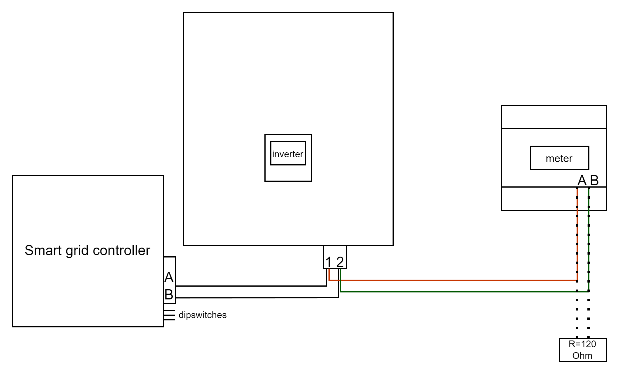
| Device | SmartgridOne Controller model OM1 | SmartgridOne Controller model IG8 | RS485-USB converter | RS485-Ethernet converter |
|---|---|---|---|---|
| Pin 1 / Modbus-485_B | RS485 A | RS485_POS | RS485 A | TX+ |
| Pin 2 / Modbus-485_A | RS485 B | RS485_NEG | RS485 B | TX- |
| Pin 3 / GND_485 | RS GND | GND | Not available | G |
Configuration
NOTE: RS485 Device Addresses
- You MUST give each device on the RS485 bus a unique address. Check the manual of the device on how to do this.
- Use lower addresses first (1, 2, ...) because the SmartgridOne Controller will find them faster!
- For each device, it is generally recommended to stick with the factory default baud rate, parity, and stop bits. The SmartgridOne Controller will scan on those first.
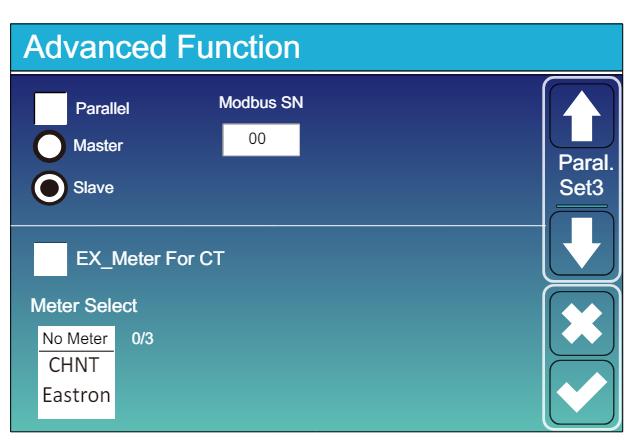
Go to “Main Screen” >> “System Settings” >> “Advanced Function.”
- Modbus SN should be set to any number between 1 and 247. Do not select 0!! Note that if there are multiple devices on the RS485 bus, each should be given a unique number. This is the address.
- Slave should be checked.
- Only when an additional meter is connected directly to the inverter should “EX_meter For CT” be checked. If there is only a meter in parallel with the SmartgridOne Controller it should be unchecked.
- Make sure the following settings are all correct: "Max A Charge", "Max A Discharge", "Grid Charge Ampere"