Alfen charging stations
This guide will serve as a guide to adjust the Alfen charging station settings to allow communication with and control by the SmartgridOne Controller. For more in depth information you can use the Alfen Smart charging implementation guide
Supported Devices
| Device Type | Modbus TCP (Ethernet) | RS485 |
|---|---|---|
| Most Alfen charging stations | ✅ | ❌ |
Configuration
Install the charging station.
-
Update the Alfen charging station to firmware version 4.2.0 (or higher).
-
Connect the Alfen charging station to a network with the following requirements:
- The charging station is in the same local network as the SmartgridOne Controller.
- Make sure the communication between the charging station and the SmartgridOne Controller is open.
-
Install the ACE service installer tool, or search for the latest version of the ACE service installer on the internet if the link does not work.
-
Create a valid account for Alfen ACE Service Installer now (to be requested via https://support.alfen.com)
-
To control the charging station, the smart charging functionality must first be purchased and then rolled out.
-
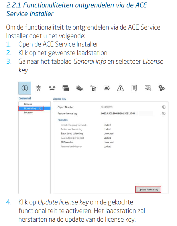
Unlocking functionality via the ACE Service Installer: to unlock functionality via the ACE Service Installer, do the following:
-
Open the ACE Service Installer
-
Click on the desired charging station
-
Go to the General info tab and select License key
-
Click Update license key to activate the purchased functionality. The charging station will restart after the license key is updated.
-
-
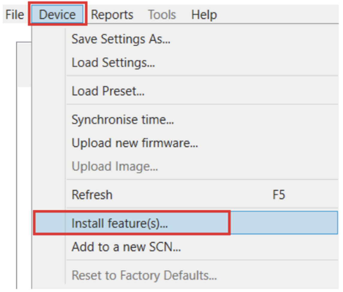
If the location has a weak internet connection, the following procedure can be used to unlock the desired functionality:
-
Open the ACE Service Installer
-
Go to Device in the menu
-
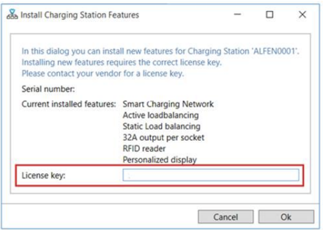
Select Install feature(s)
-
Enter the license key and click OK. The charging station will restart after the license key is updated.
-
-
-
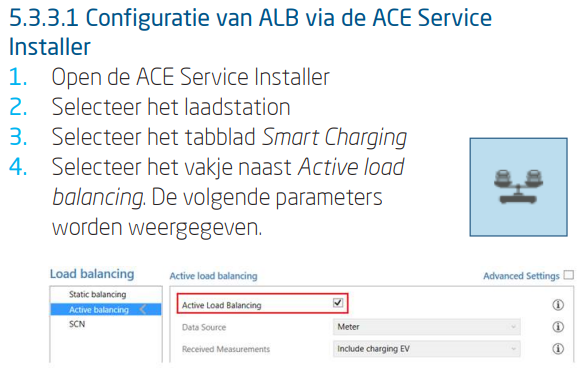
Configuring ALB via the ACE Service Installer
-
Open the ACE Service Installer
-
Select the charging station
-
Select the Smart Charging tab
-
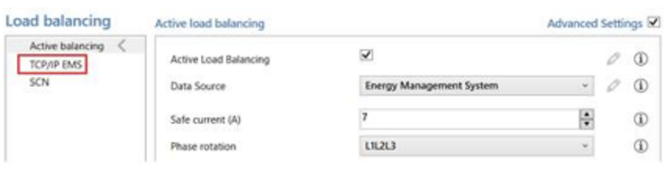
Check the box next to Active load balancing. The following parameters are displayed.
-
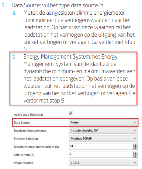
Data Source; enter the data source type:
- Energy Management System: The customer's Energy Management System will transmit the dynamic minimum and maximum values to the charging station. Based on these values, the charging station will increase or decrease the power output from the socket.
-
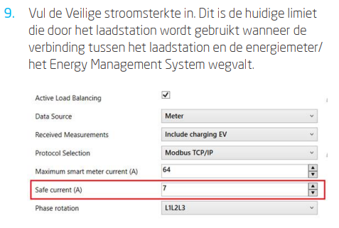
Enter the Safe current. This is the current limit the charging station uses when the connection between the charging station and the energy meter/Energy Management System is lost.
-
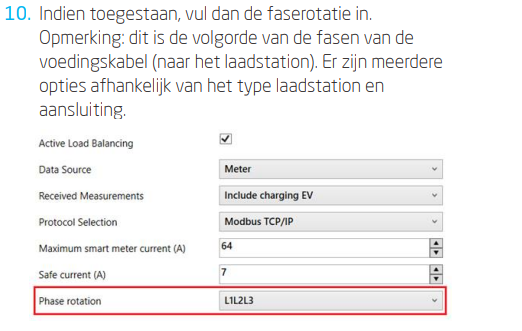
If permitted, enter the phase rotation. Note: This is the phase sequence of the power cable (to the charging station). There are several options depending on the type of charging station and connection.
-
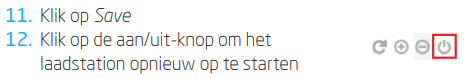
Click Save
-
Click the power button to restart the charging station.
-
-
Configuring an EMS via the ACE Service Installer
-
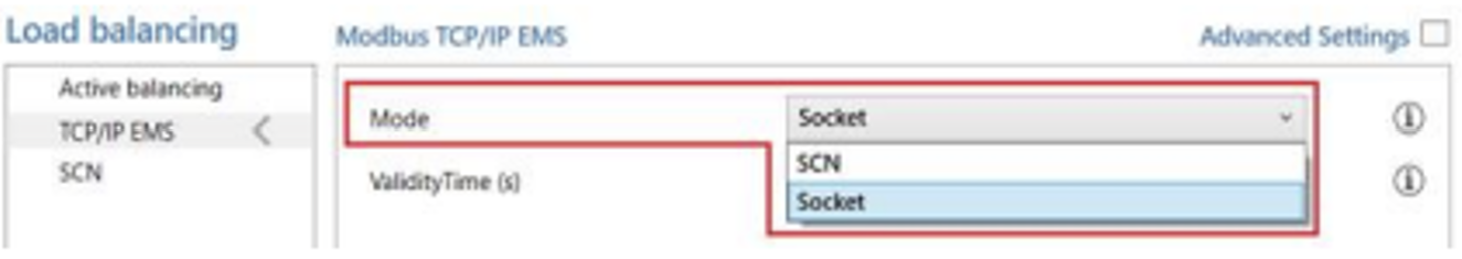
If the Energy Management System is selected as the data source (see step 6: "Configuring ALB via the ACE Service Installer"), an additional page will appear on the screen. Double-click to open the screen. Select TCP/IP EMS in the menu.
-
Enter the mode. Select whether the EMS manages each individual socket or an entire Smart Charging Network.
-
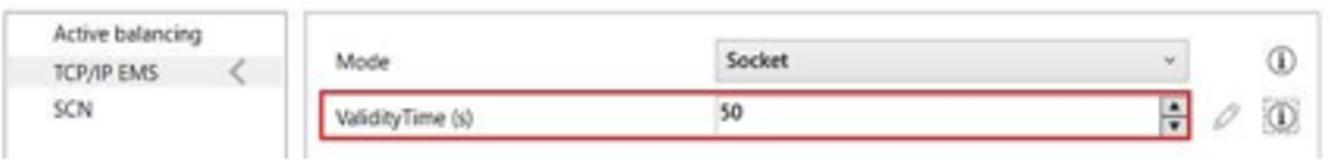
Enter the validity period (default 60 s). If the charging station has not received updates from the EMS within the configured validity period, it will interpret this as a disconnection and will return to the configured safe current.
-
-
Test the connection of a ALB with a EMS
-
Configure the installation according to the instructions in the previous steps.
-
Go to the Live Monitoring tab, select States, and observe the Modbus TCP/IP connection status as shown below:
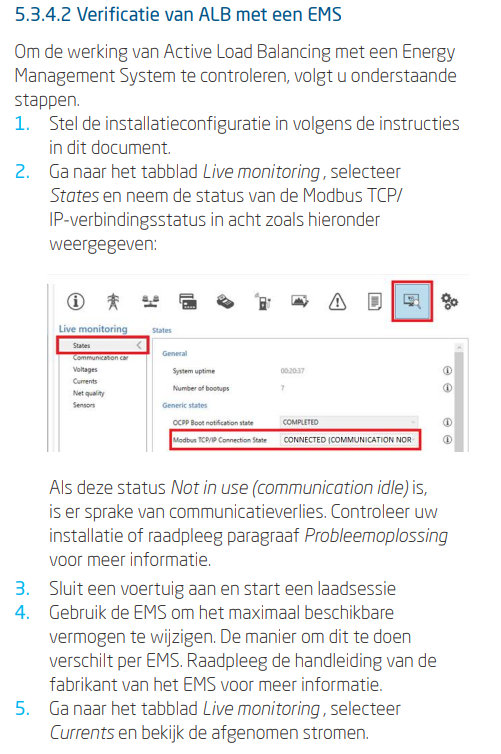
If this status is Not in use (communication idle), there is a loss of communication. Check your installation or consult the Troubleshooting section for more information.
-
Connect a vehicle and start a charging session.
-
Use the EMS to change the maximum available power. The method for doing this varies by EMS. Consult the EMS manufacturer's manual for more information.
-
Go to the Live Monitoring tab, select Currents, and view the currents being drawn.
-