
TODO: Wygląda na to, że dotyczy to więcej falowników?

Falowniki serii Sofar TL-G3 i TLM/X-G3
Obsługiwane urządzenia
| Device Type | Modbus TCP (Ethernet) | RS485 | Curtailment |
|---|---|---|---|
| ... | ✅ | ✅ | ✅ |
| 1100-3300TL-G3 | |||
| 3000-7500TLM | |||
| 10000-40000TL | |||
| 5000-80000TLX-G3 | |||
| 100000-125000TLX-G4 | |||
| 7000-10500TLM-G3 |
Ostrzeżenie
Ostrzeżenie
- Większość urządzeń może komunikować się za pomocą Modbus TCP. Nie dotyczy to serii "SOFAR 1...40KTL".
- Niektóre falowniki wymagają specjalnego oprogramowania sprzętowego ograniczonego do wybranych dystrybutorów. W razie wątpliwości skonsultuj się ze swoim dystrybutorem.
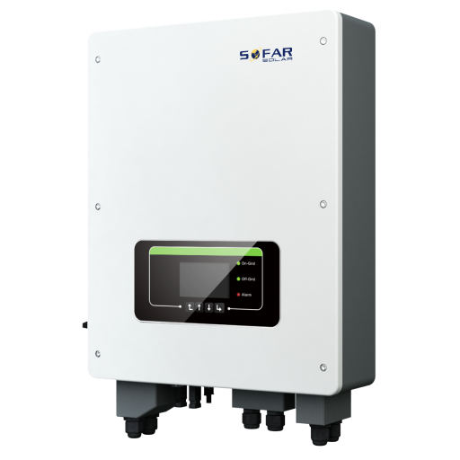
Okablowanie
Ethernet
Podłącz falownik do sieci internetowej za pomocą "SOFAR SOLAR ETHERNET STICK LSE3".
Aby poprawnie poprowadzić okablowanie Ethernet: Postępuj zgodnie z wytycznymi dotyczącymi okablowania Ethernet.
RS485
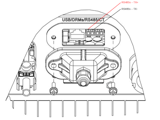
...TL-G3 & G1 & G2
Informacja
RS485 Wiring
- For correct RS485 wiring: Follow the guidelines for RS485 wiring.
- If the wiring shown in the table below is incorrect, please let us know.
- There is no general consensus in the industry about the usage of A and B for the RS485 polarity, so it may be counterintuitive and opposite of what you might expect for some devices.
| Device | SmartgridOne Controller model OM1 | SmartgridOne Controller model IG8 | RS485-USB converter | RS485-Ethernet converter |
|---|---|---|---|---|
| RS485s TR+ | RS485 A | RS485_POS | RS485 A | TX+ |
| RS485s TR- | RS485 B | RS485_NEG | RS485 B | TX- |
| N/A | RS GND | GND | Not available | G |
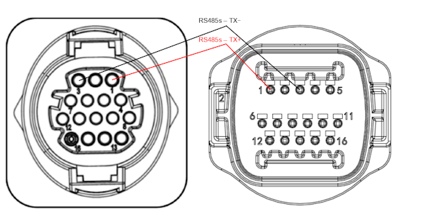
...TLX & TLM
Informacja
RS485 Wiring
- For correct RS485 wiring: Follow the guidelines for RS485 wiring.
- If the wiring shown in the table below is incorrect, please let us know.
- There is no general consensus in the industry about the usage of A and B for the RS485 polarity, so it may be counterintuitive and opposite of what you might expect for some devices.
| Device | SmartgridOne Controller model OM1 | SmartgridOne Controller model IG8 | RS485-USB converter | RS485-Ethernet converter |
|---|---|---|---|---|
| RS485s TR+ (pin 1) | RS485 A | RS485_POS | RS485 A | TX+ |
| RS485s TR- (pin 3) | RS485 B | RS485_NEG | RS485 B | TX- |
| N/A | RS GND | GND | Not available | G |
Konfiguracja
RS485
Ostrzeżenie
NOTE: RS485 Device Addresses
- You MUST give each device on the RS485 bus a unique address. Check the manual of the device on how to do this.
- Use lower addresses first (1, 2, ...) because the SmartgridOne Controller will find them faster!
- For each device, it is generally recommended to stick with the factory default baud rate, parity, and stop bits. The SmartgridOne Controller will scan on those first.
Zewnętrzna kontrola falownika musi być aktywowana w menu konfiguracji falownika poprzez ekran LCD.
- Kliknij krótko przycisk w dół.
- Zobaczysz "1. Enter settings", przytrzymaj przycisk w dół przez 2 sekundy, aby wejść do ustawień.
- Przejdź przez ustawienia, aż zobaczysz:
- Modbus Address lub
- Set ComProtocol
- Przytrzymaj przycisk w dół przez 2 sekundy, aby ustawić adres.
- Ustaw adres na żądaną wartość.
Last updated August 18, 2026Edit this page