Xargeon / ZhongDe Energy
La SmartgridOne Controller supporta due versioni della linea di prodotti booster. Il booster è un caricatore rapido DC con batteria integrata. Tipicamente la batteria viene utilizzata per supportare la rete quando si carica un VE ad alta potenza, ma può essere usata per altri scopi.
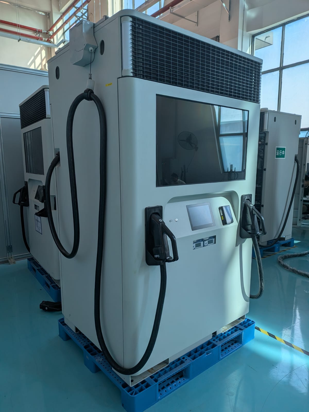
Dispositivi Supportati
| Device Type | Modbus TCP (Ethernet) | RS485 |
|---|---|---|
| Xargeon Booster generation 1 | ✅ | ❌ |
| Xargeon Booster generation 2 |
Configurazione
[!DANGER]
Avvertenza di sicurezza: rischio di folgorazione
Disconnettere l'alimentazione prima di eseguire i passaggi seguenti. Quando il pannello posteriore è aperto, espone un bus DC ad alta tensione a 800v.
Prerequisiti: Il sistema deve essere installato fisicamente e collegato all'alimentazione seguendo il manuale di installazione. La guida sottostante copre solo l'installazione della comunicazione con la rete e con la SmartgridOne Controller.
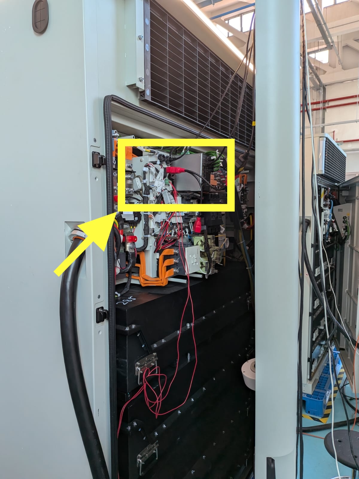
Passo 1: La comunicazione tra la SmartgridOne Controller e il Xargeon Booster avviene tramite Modbus TCP. Spegnere l'alimentazione e aprire il pannello posteriore del booster. Concentrarsi sulla parte evidenziata nella foto:
Passo 2: Usare due cavi ethernet per collegare:
- Giallo: l'interfaccia per Modbus TCP. Questo cavo può essere collegato a uno switch di rete nello stesso sottorete della SmartgridOne Controller.
- Arancione: l'interfaccia per internet. Questa è usata, tra l'altro, per l'interfaccia di pagamento.
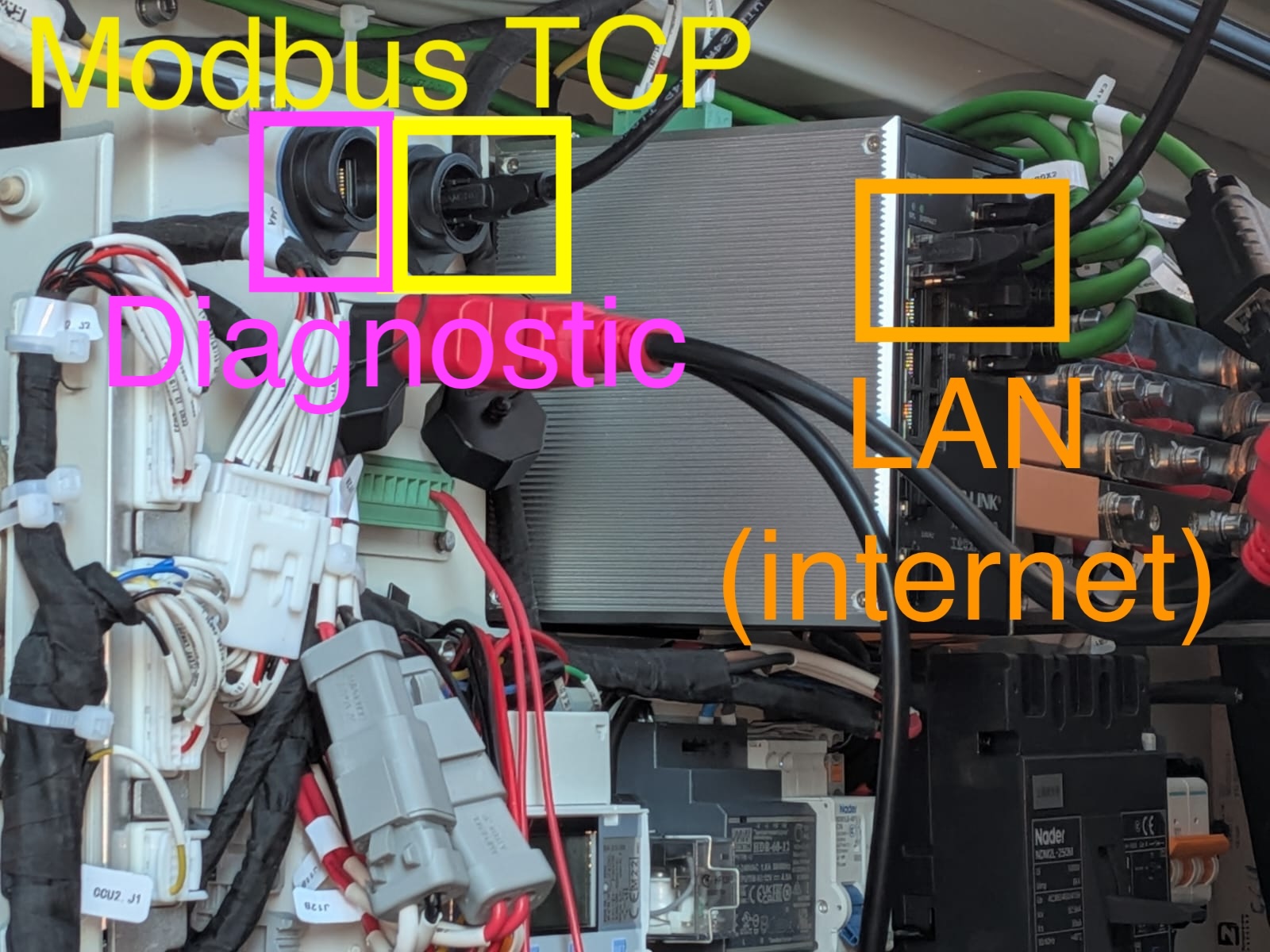
Passo 3: Solo per il commissioning: Collegare il computer direttamente con un cavo LAN all'interfaccia diagnostica del Booster. Questa è l'interfaccia segnata in viola nell'immagine sopra. Dopo il commissioning, questa interfaccia non è più necessaria.
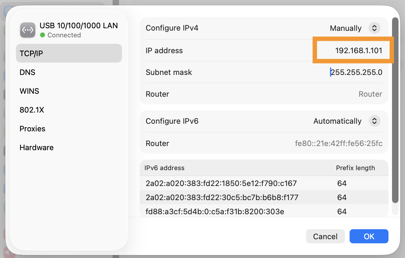
Passo 4: Aprire le impostazioni di rete sul computer e assegnare manualmente l'indirizzo IP 192.168.1.101:
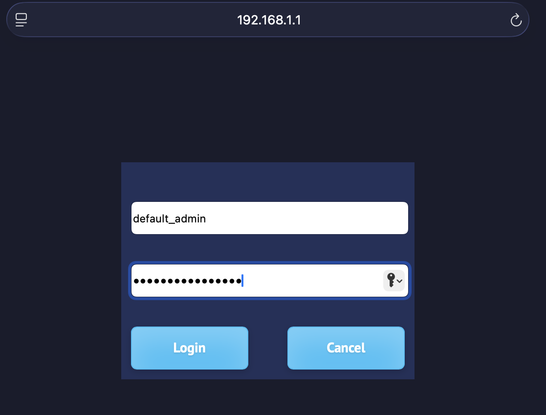
Passo 5: Aprire il browser e andare su https://192.168.1.1/. Procedere oltre gli avvisi di sicurezza se il browser segnala una pagina non sicura.
Il nome utente di default è default_admin e la password di default è Default_Admin22! (prestare attenzione alle lettere maiuscole).
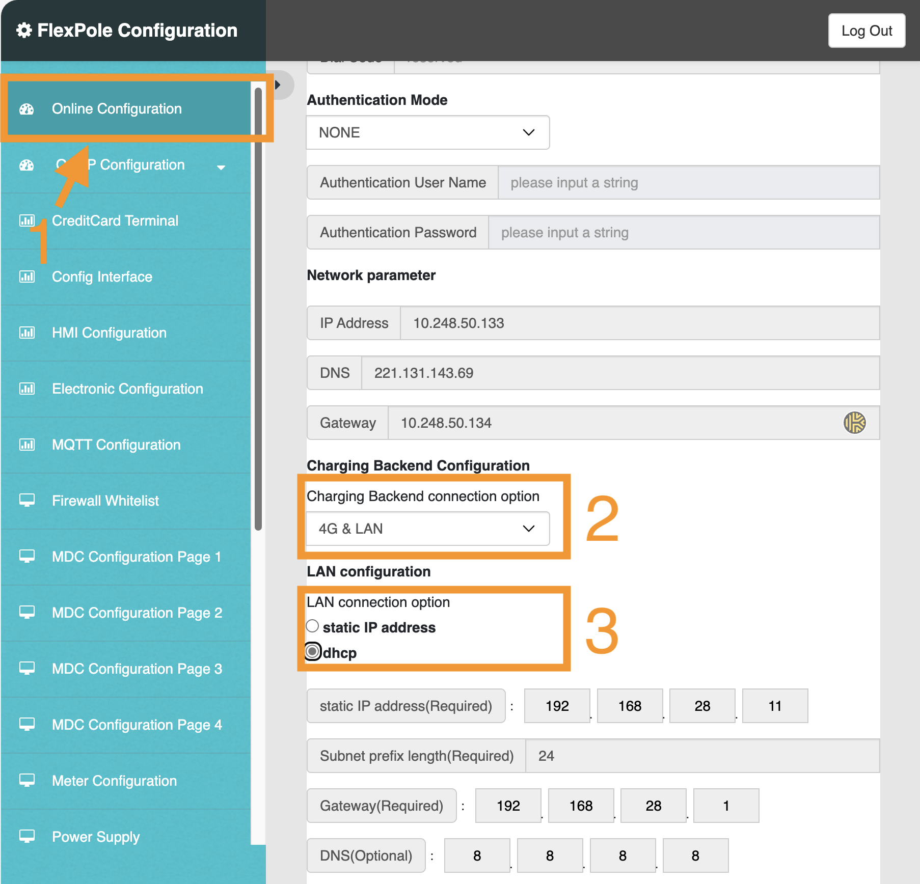
Passo 6: Nella barra laterale, selezionare 'Online configuration', e scorrere la pagina verso il basso. Regolare le impostazioni in base alle aree segnate nell'immagine sottostante:
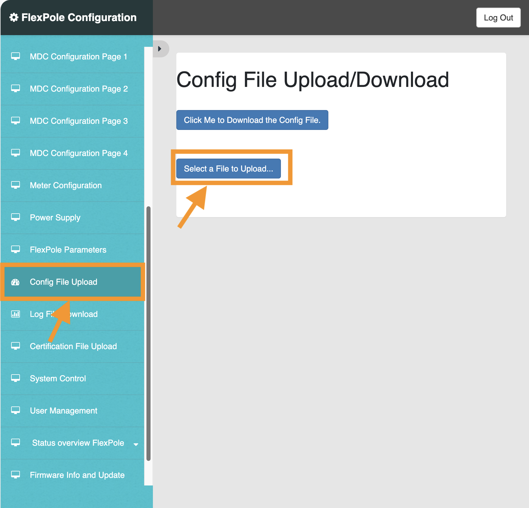
Passo 7: In questo passo, dobbiamo caricare un file di impostazioni per abilitare il controllo remoto.
IMPORTANTE: Questo file di impostazioni deve essere fornito da Xargeon. SmartgridOne, né voi stessi potete creare questo file di impostazioni in quanto il file è accettato solo se firmato elettronicamente da Xargeon.
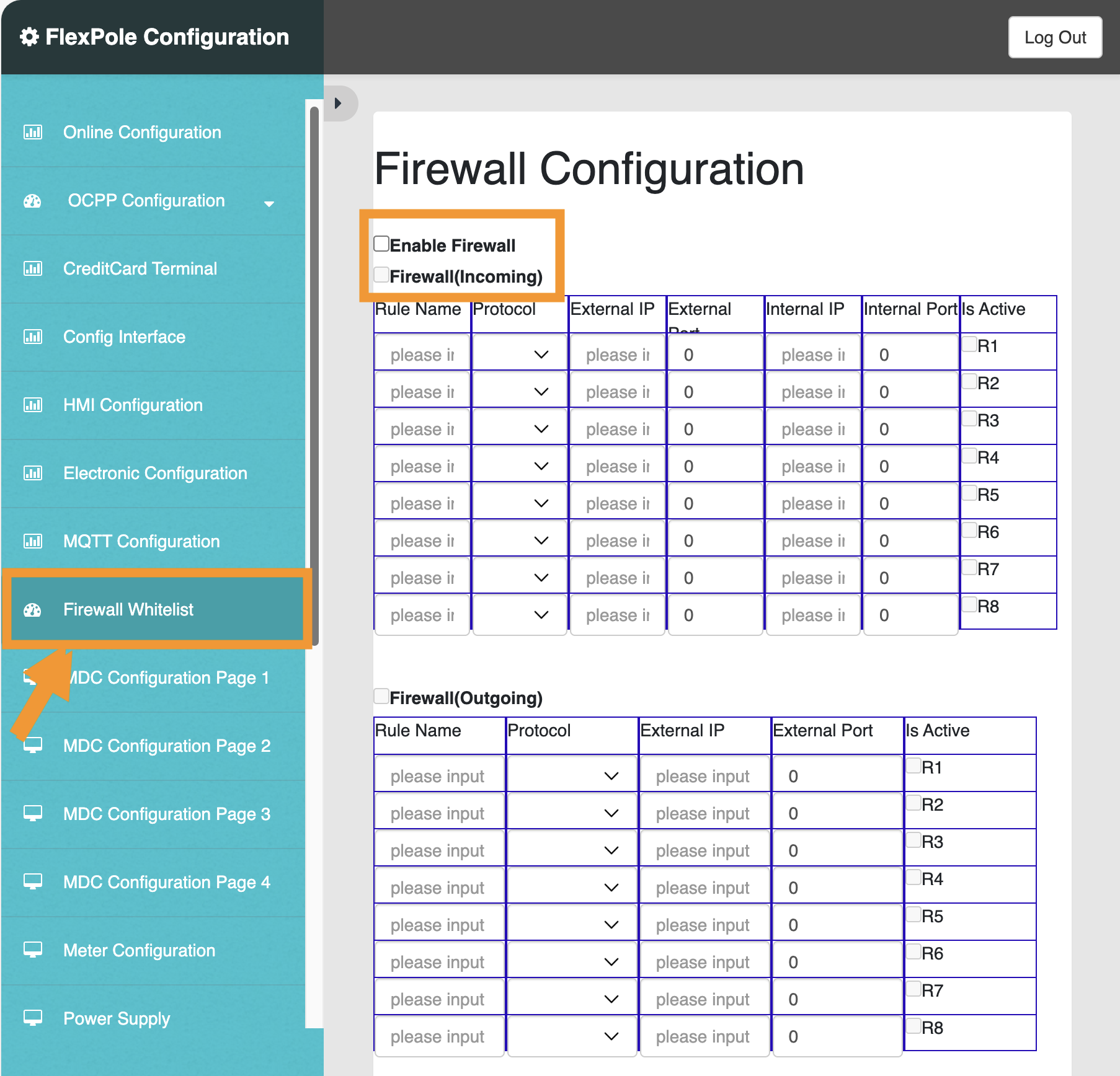
Passo 8: Verificare le impostazioni del firewall. Avete due opzioni:
- Disabilitare completamente il firewall. Questa è l'opzione più semplice ma dovrebbe essere usata solo in ambienti sicuri.
- Abilitare il firewall e creare una voce nella whitelist per la SmartgridOne Controller sulla porta 502. Qui va usato l'indirizzo IP della SmartgridOne Controller.
Completato: Il sistema è ora pronto per la connessione con la SmartgridOne Controller. Procedere nell'interfaccia SmartgridOne Controller per trovare il dispositivo nella procedura guidata.
Impostazioni
Note tecniche
Booster generazione 2
Modalità di controllo
Il Booster generazione 2 presenta le seguenti caratteristiche:
- Convertitore AC/DC da 80 kW
- Connettore VE 1: 200 kW DC
- Connettore VE 2: 210 kW DC
- Batteria con capacità energetica di 218 kWh; capacità di potenza di 240 kW
Questo significa che la batteria può essere scaricata o caricata solo con 80 kW dalla e verso la rete. La potenza di scarica arriva fino a 200 kW quando scaricata in DC destinata alla ricarica del VE. In base alla potenza di controllo della batteria, si alternano due modalità fornite da Xargeon:
- Modalità ricarica: attivata quando la batteria è caricata dal lato AC o quando il setpoint della batteria è 0. Quando attiva, la potenza di ricarica del VE è limitata a 200 per il connettore VE 1 e 210 kW DC per il connettore VE 2 (combinati fino a 240 kW)
- Modalità immissione: attivata quando la batteria è scaricata dal lato AC. Quando attiva, la potenza di ricarica del VE è limitata a 130 per il connettore VE 1 e 140 kW DC per il connettore VE 2 (combinati fino a 160 kW).
Stato minimo di carica
Di default, lo stato minimo di carica è impostato al 10%. Quando si scarica a questo livello, dovrebbe essere ricaricata fino al 20% prima di scaricarla di nuovo.