Adding Fluvius Telecontrole RTU
The manual describes the steps to set up the Fluvius Telecontrole RTU on the SmartgridOne Controller.
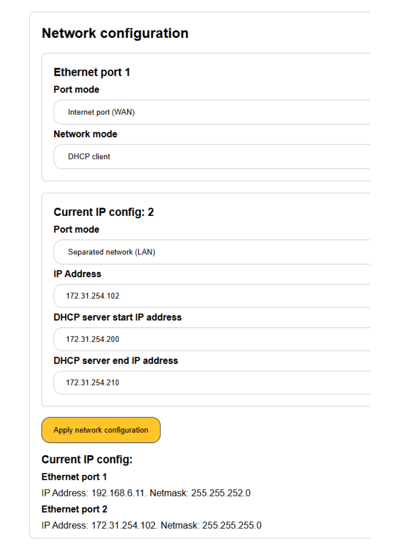
Step 1: Network configuration
Required network configuration for Fluvius on network port 2 (this is the upper port of the two – connect this to the Fluvius RTU):
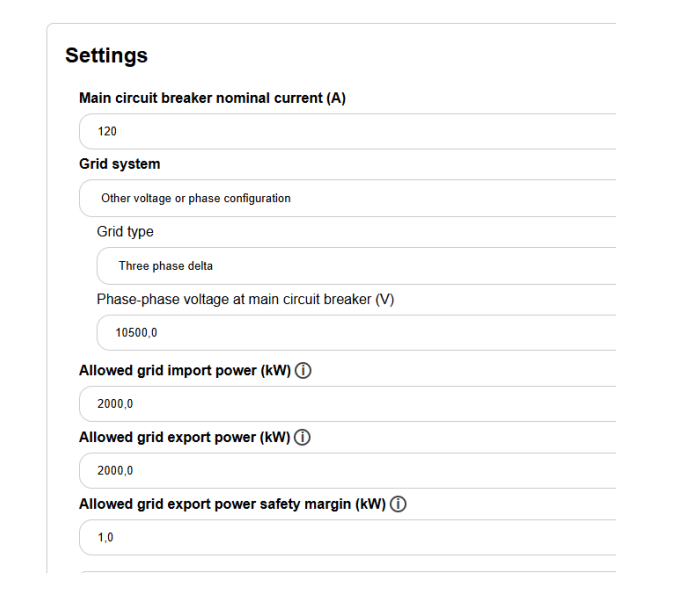
Step 2: Verify the voltages of the devices
For certain reactive power control modes, the medium voltage must be measured. If the main grid meter measures the medium voltage grid, then in the settings make sure to set this correctly:
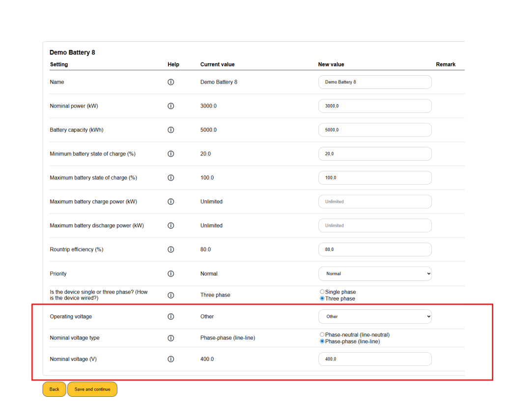
If there are also lower voltage devices in the system, you must adjust their voltage settings as well in the device settings. For example:
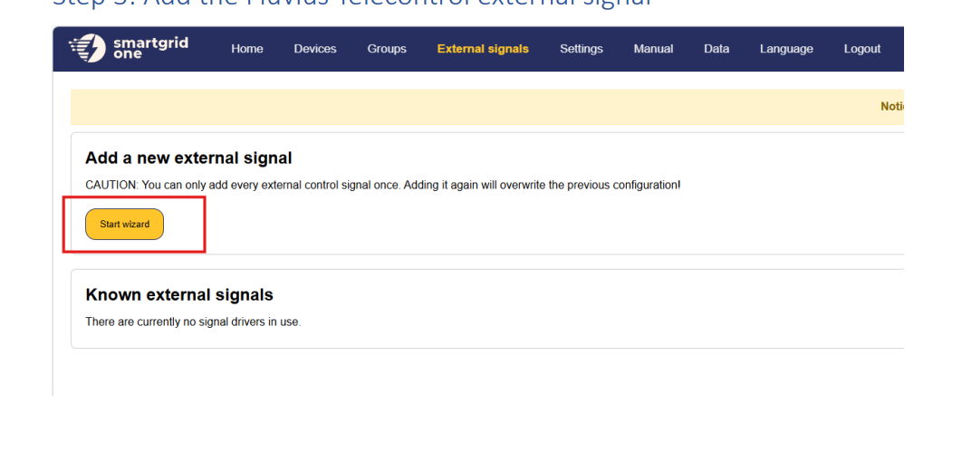
Step 3: Add the Fluvius Telecontrol external signal
1. Click on 'External Signals' in the top menu and click on the 'Start wizard' button.
2. Choose 'Distribution system operator / grid operator', select 'Fluvius', then select 'Fluvius Telecontrole' as the data source and click 'Next'.

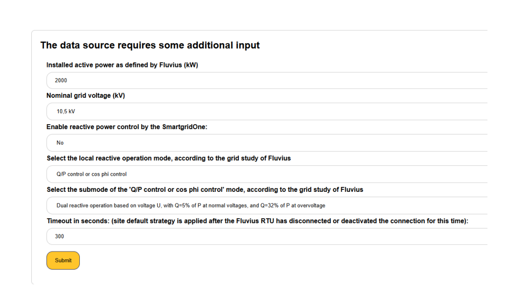
3. Fill in the required information and click 'Submit'.
- Installed active power as defined by Fluvius (kW): The installed active power as agreed upon with Fluvius.
- Nominal grid voltage (kV): The nominal voltage of the grid to which the installation is connected.
- Enable reactive power control by the SmartgridOne Controller: Whether the Controller performs reactive power control.
- Local reactive operation mode: The reactive operation mode according to the grid study of Fluvius (e.g. 'Q/P control or cos phi control').
- Submode of the reactive operation mode: The submode according to the grid study of Fluvius.
- Timeout (seconds): The site default strategy is applied after the Fluvius RTU has disconnected or deactivated the connection for this time.
Tip
Tip
First test with reactive power control disabled, and then enable it. This helps separate active and reactive power control.
Last updated June 9, 2026Edit this page