Shelly relays can be used to control heat pumps with smartgrid ready contacts. See Smartgrid Ready Contacts for more information on smartgrid ready contacts.
Supported Devices
| Device Type | Variants | Local API |
|---|---|---|
| Shelly Plus | 2PM, Uni | ✅ |
| Shelly Pro | 2, 2PM, 3, 4PM | |
| Shelly Gen3 | 2PM, 2L | |
| Shelly Gen4 | 2PM, PowerStrip |
Note
Please note: This integration has not been tested with all the devices listed above. However, since they utilize the same communication protocol, they are expected to operate seamlessly.
Configuration examples in this document are based on the Shelly Pro 2 relay.
Wiring
The communication between the Controller and the Shelly relay is established via Local API (over TCP/IP). For proper Ethernet wiring, please follow the Ethernet wiring guidelines.
Wiring Instructions
-
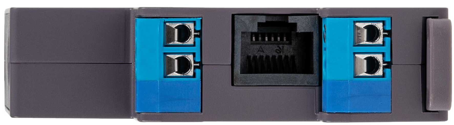
Power Supply Connections
- L (Live): Connect the live wire to the L terminal of the device.
- N (Neutral): Connect the neutral wire to the N terminal of the device.
-
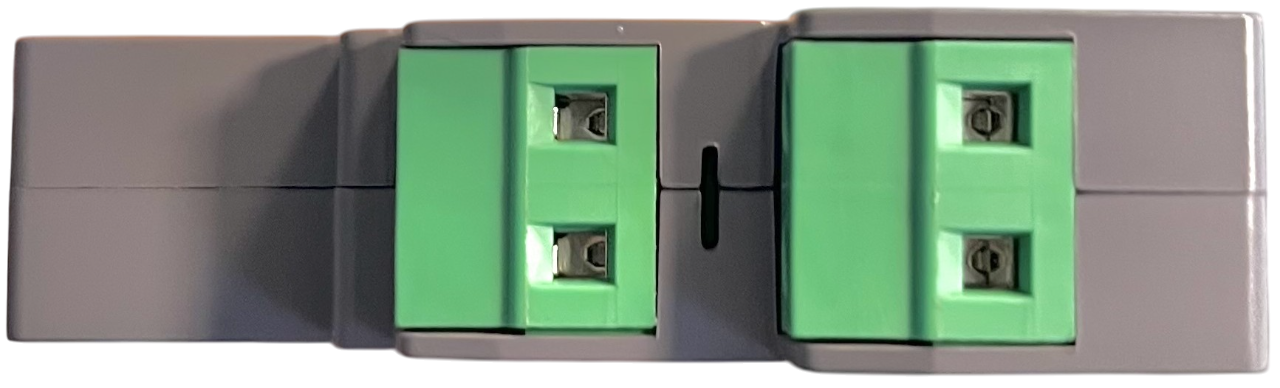
Relay Output Connections
- O1 (Relay 1): Connect the live wire for the first circuit to the O1 terminal.
- O2 (Relay 2): Connect the live wire for the second circuit to the O2 terminal.
-
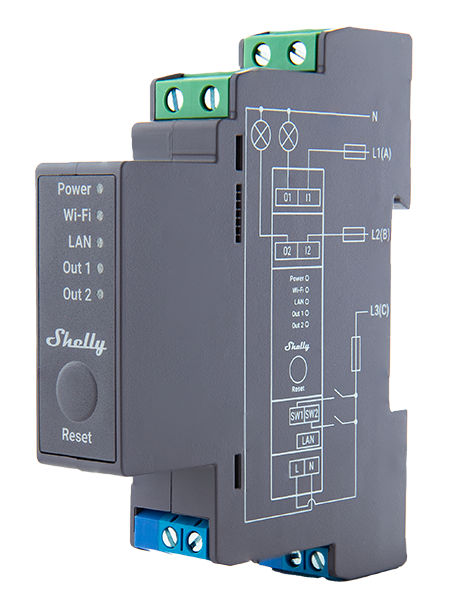
Device Diagram
Refer to the diagram printed on the device for detailed wiring instructions. Ensure all connections match the diagram.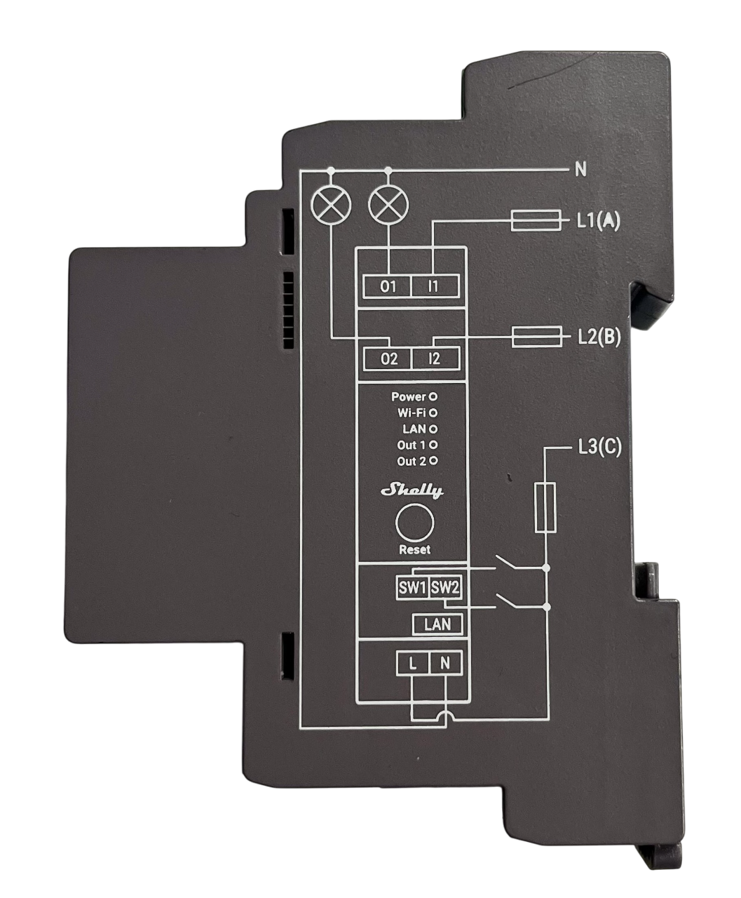
Configuration Instructions
-
Wire the Device
Ensure the device is wired according to the provided wiring diagram and connect the Ethernet cable securely.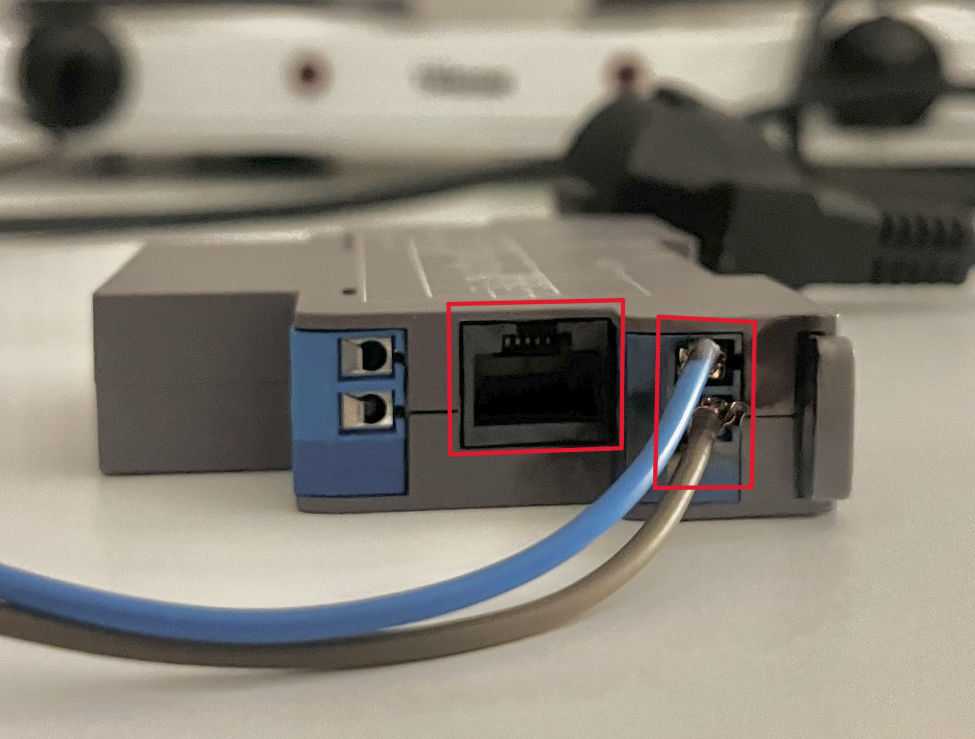
-
Access the Shelly Interface
- Using a phone or other device, connect to the Shelly relay's Wi-Fi network (e.g. SSID: ShellyPro2-XXXXXX).
- Open a browser and navigate to http://192.168.33.1 to access the Shelly interface.
-
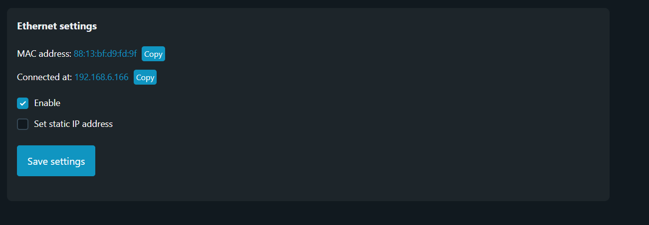
Locate the Ethernet Settings
- In the Shelly interface, navigate to the Ethernet Settings section.
- Here, you will find the assigned Ethernet IP address, which is required for connecting the device to the controller.

Note
Note: Do not modify any settings while locating the Ethernet IP address.
By following these steps, you will retrieve the required IP address for integrating the Shelly relay with the Controller. For further details and comprehensive documentation, please refer to the official Shelly Installation Guides.