TODO: It looks like this is valid for more inverters?
Sofar TL-G3 and TLM/X-G3 Series Inverters
Supported Devices
| Device Type | Modbus TCP (Ethernet) | RS485 | Curtailment |
|---|---|---|---|
| ... | ✅ | ✅ | ✅ |
warning
- Most of the devices can communicate using modbus TCP. This is not valid for the series "SOFAR 1...40KTL"
- Some inverters require specific firmware that is limited to certain distributors. Consult your distributor in case of doubt.
TODO: Complete the table
Wiring
Ethernet
Connect the inverter to your internet network using the "SOFAR SOLAR ETHERNET STICK LSE3".
For correct ethernet wiring: Follow the the guidelines for ethernet wiring.
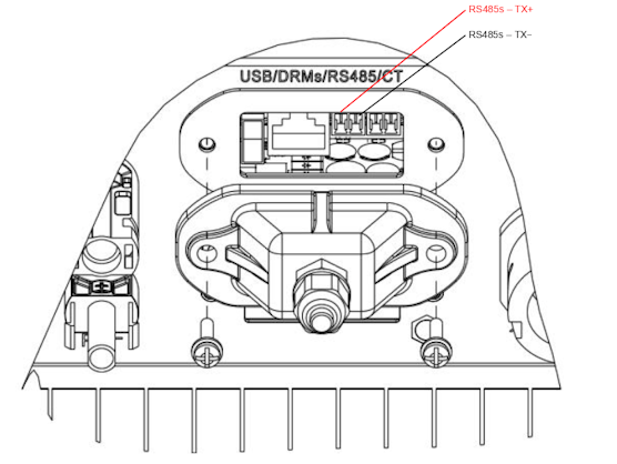
RS485
...TL-G3 & G1 & G2
RS485 Wiring
- For correct RS485 wiring: Follow the guidelines for RS485 wiring.
- If the wiring shown in the table below is incorrect, please let us know.
- There is no general consensus in the industry about the usage of A and B for the RS485 polarity, so it may be counterintuitive and opposite of what you might expect for some devices.
| Device | SmartgridOne Controller model OM1 | SmartgridOne Controller model IG8 | RS485-USB converter | RS485-Ethernet converter |
|---|---|---|---|---|
| RS485s TX+ | RS485 A | RS485_POS | RS485 A | TX+ |
| RS485s TX- | RS485 B | RS485_NEG | RS485 B | TX- |
| N/A | RS GND | GND | Not available | G |
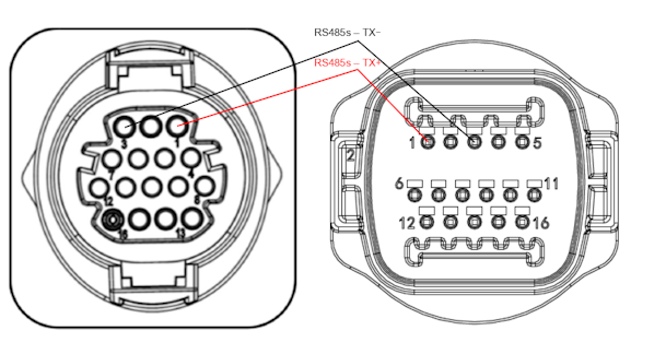
...TLX & TLM
RS485 Wiring
- For correct RS485 wiring: Follow the guidelines for RS485 wiring.
- If the wiring shown in the table below is incorrect, please let us know.
- There is no general consensus in the industry about the usage of A and B for the RS485 polarity, so it may be counterintuitive and opposite of what you might expect for some devices.
| Device | SmartgridOne Controller model OM1 | SmartgridOne Controller model IG8 | RS485-USB converter | RS485-Ethernet converter |
|---|---|---|---|---|
| RS485s TX+ (pin 1) | RS485 A | RS485_POS | RS485 A | TX+ |
| RS485s TX- (pin 3) | RS485 B | RS485_NEG | RS485 B | TX- |
| N/A | RS GND | GND | Not available | G |
Configuration
RS485
NOTE: RS485 Device Addresses
- You MUST give each device on the RS485 bus a unique address. Check the manual of the device on how to do this.
- Use lower addresses first (1, 2, ...) because the SmartgridOne Controller will find them faster!
- For each device, it is generally recommended to stick with the factory default baud rate, parity, and stop bits. The SmartgridOne Controller will scan on those first.
External inverter control must be activated in the configuration menu of the inverter via the LCD screen.
- Click shortly on the button down.
- You'll see "1. Enter settings", press button down for 2 seconds to enter the settings.
- Go through the settings until you see:
- Modbus Address or
- Set ComProtocol
- Press button down for 2 seconds to set the address.
- Set the Address to the wanted value.