DEYE
Dispositivos Suportados
| Device Type | Variants | Modbus TCP (Ethernet) | RS485 | Curtailment |
|---|---|---|---|---|
| SG04LP3-EU | SUN-5/6/8/10/12K | ❌ | ✅ | ❌ |
| SG01LP1-EU | SUN-12/14/16K |
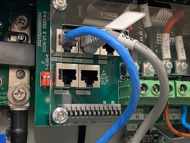
Fiação
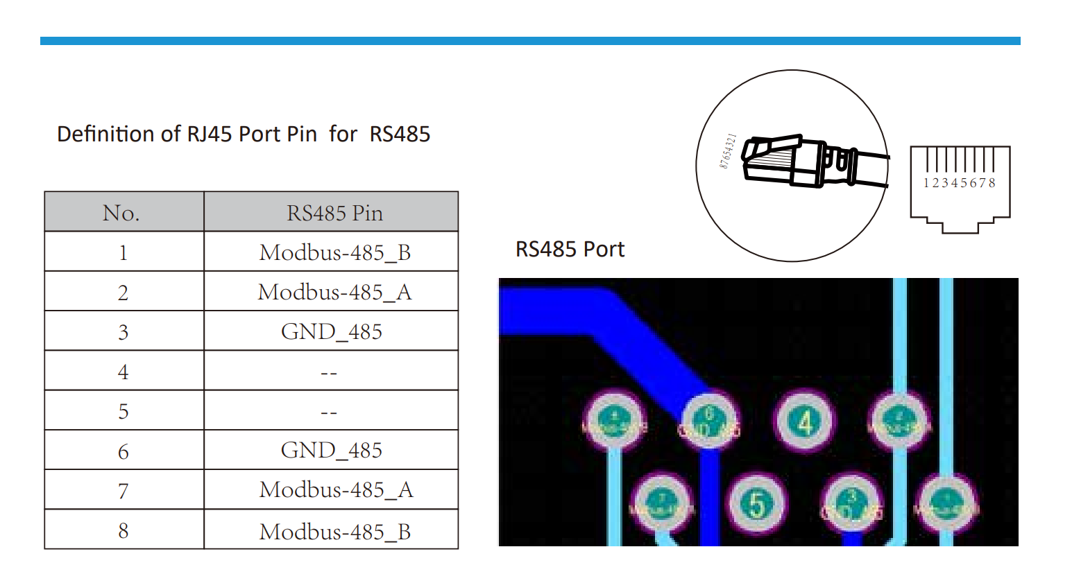
RS485
RS485 Wiring
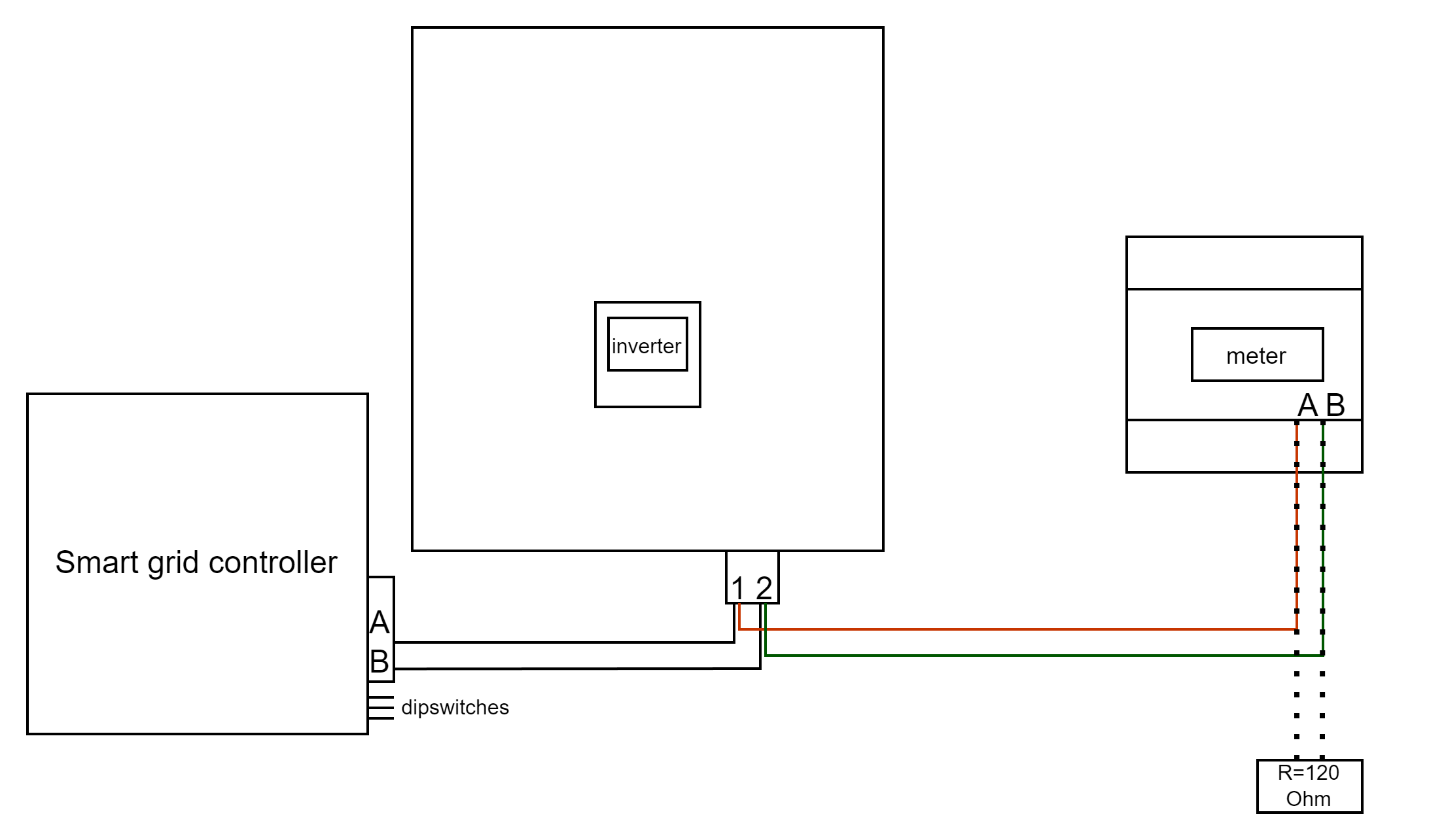
- For correct RS485 wiring: Follow the guidelines for RS485 wiring.
- If the wiring shown in the table below is incorrect, please let us know.
- There is no general consensus in the industry about the usage of A and B for the RS485 polarity, so it may be counterintuitive and opposite of what you might expect for some devices.
| Device | SmartgridOne Controller model OM1 | SmartgridOne Controller model IG8 | RS485-USB converter | RS485-Ethernet converter |
|---|---|---|---|---|
| Pino 1 / Modbus-485_B | RS485 A | RS485_POS | RS485 A | TX+ |
| Pino 2 / Modbus-485_A | RS485 B | RS485_NEG | RS485 B | TX- |
| Pino 3 / GND_485 | RS GND | GND | Not available | G |
Configuração
NOTE: RS485 Device Addresses
- You MUST give each device on the RS485 bus a unique address. Check the manual of the device on how to do this.
- Use lower addresses first (1, 2, ...) because the SmartgridOne Controller will find them faster!
- For each device, it is generally recommended to stick with the factory default baud rate, parity, and stop bits. The SmartgridOne Controller will scan on those first.
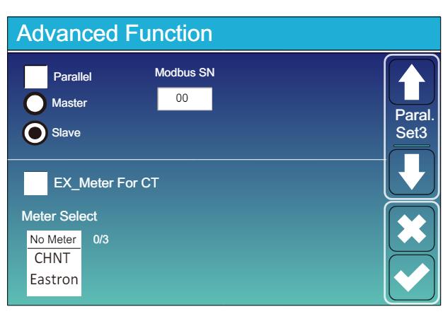
Vá para “Tela Principal” >> “Configurações do Sistema” >> “Função Avançada.”
- O SN Modbus deve ser definido para qualquer número entre 1 e 247. Não selecione 0!! Observe que, se houver vários dispositivos no barramento RS485, cada um deve receber um número único. Este é o endereço.
- O Slave deve estar marcado.
- Somente quando um medidor adicional estiver conectado diretamente ao inversor, “EX_meter For CT” deve ser marcado. Se houver apenas um medidor em paralelo com o SmartgridOne Controller, isso deve estar desmarcado.
- Certifique-se de que as seguintes configurações estão todas corretas: "Max A Charge", "Max A Discharge", "Grid Charge Ampere"