Cabeamento RS485 da série LH Autarco
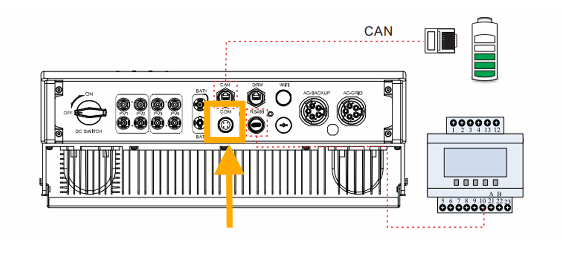
Esta página descreve a comunicação com um inversor híbrido da série Autarco LH via Modbus-RTU (rs485). Por padrão, o inversor está configurado para o endereço 1. A interface RS485 é um conector de 4 pinos chamado "COM" localizado na parte inferior do inversor atrás de uma placa protetora. A posição exata está marcada na caixa laranja na imagem abaixo:
Vendo mais de perto, a porta se parece com isso:
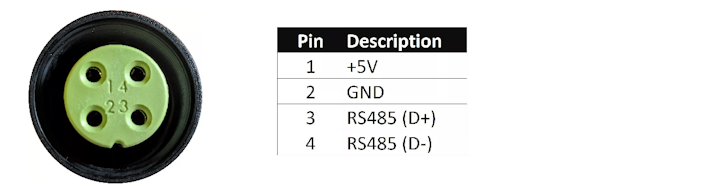
Um conector apropriado deve ser usado para este conector de 4 pinos no inversor Autarco para conectar ao SmartgridOne Controller. No SmartgridOne Controller, o inversor pode ser conectado à porta RS485. A fiação é a seguinte:
RS485 Wiring
- For correct RS485 wiring: Follow the guidelines for RS485 wiring.
- If the wiring shown in the table below is incorrect, please let us know.
- There is no general consensus in the industry about the usage of A and B for the RS485 polarity, so it may be counterintuitive and opposite of what you might expect for some devices.
| Device | SmartgridOne Controller model OM1 | SmartgridOne Controller model IG8 | RS485-USB converter | RS485-Ethernet converter |
|---|---|---|---|---|
| Pino 3 | RS485 A | RS485_POS | RS485 A | TX+ |
| Pino 4 | RS485 B | RS485_NEG | RS485 B | TX- |
| N/A | RS GND | GND | Not available | G |
NOTE: RS485 Device Addresses
- You MUST give each device on the RS485 bus a unique address. Check the manual of the device on how to do this.
- Use lower addresses first (1, 2, ...) because the SmartgridOne Controller will find them faster!
- For each device, it is generally recommended to stick with the factory default baud rate, parity, and stop bits. The SmartgridOne Controller will scan on those first.