Cablaggio RS485 serie MH Autarco
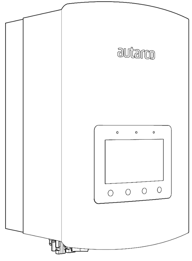
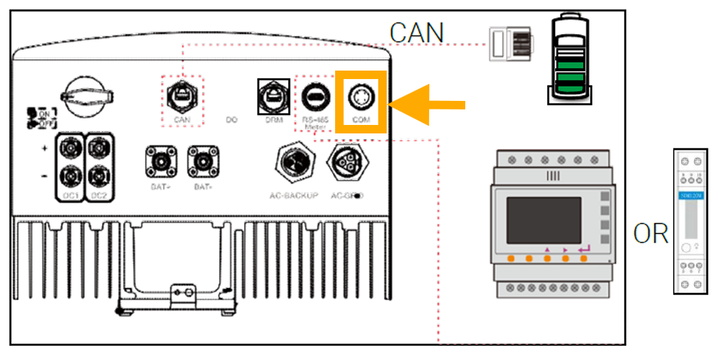
Questa pagina descrive la comunicazione con un inverter ibrido della serie LH di Autarco attraverso Modbus-RTU (rs485). Di default, l'inverter è impostato sull'indirizzo 1. L'interfaccia RS485 è un connettore a 4 pin chiamato "COM" situato nella parte inferiore dell'inverter dietro una piastra protettiva. La posizione esatta è contrassegnata nella casella arancione nell'immagine qui sotto:
Guardando da vicino, la porta appare in questo modo:
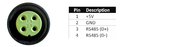
Un connettore appropriato dovrebbe essere utilizzato per questo connettore a 4 pin sull'inverter Autarco per collegarsi al SmartgridOne Controller. Sul SmartgridOne Controller, l'inverter può essere collegato alla porta RS485. Il cablaggio è il seguente:
RS485 Wiring
- For correct RS485 wiring: Follow the guidelines for RS485 wiring.
- If the wiring shown in the table below is incorrect, please let us know.
- There is no general consensus in the industry about the usage of A and B for the RS485 polarity, so it may be counterintuitive and opposite of what you might expect for some devices.
| Device | SmartgridOne Controller model OM1 | SmartgridOne Controller model IG8 | RS485-USB converter | RS485-Ethernet converter |
|---|---|---|---|---|
| Pin 3 | RS485 A | RS485_POS | RS485 A | TX+ |
| Pin 4 | RS485 B | RS485_NEG | RS485 B | TX- |
| N/A | RS GND | GND | Not available | G |
NOTE: RS485 Device Addresses
- You MUST give each device on the RS485 bus a unique address. Check the manual of the device on how to do this.
- Use lower addresses first (1, 2, ...) because the SmartgridOne Controller will find them faster!
- For each device, it is generally recommended to stick with the factory default baud rate, parity, and stop bits. The SmartgridOne Controller will scan on those first.