Câblage RS485 de la série LD d'Autarco
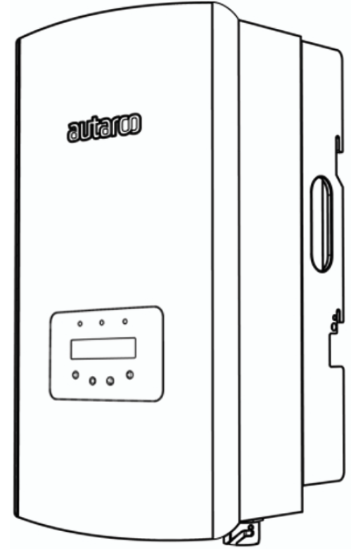
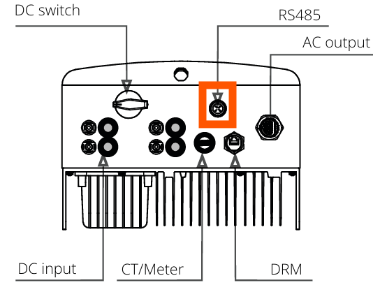
Cette page décrit la communication avec un onduleur hybride de la série Autarco LD via Modbus-RTU (rs485). Par défaut, l'onduleur est réglé sur l'adresse 1. L'interface RS485 est un connecteur à 4 broches au bas de l'onduleur derrière un panneau de protection. La position exacte est marquée dans la boîte orange de l'image ci-dessous :
De plus près, le port ressemble à ceci :
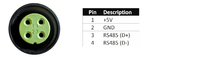
Un connecteur approprié doit être utilisé pour ce connecteur à 4 broches sur l'onduleur Autarco afin de se connecter au SmartgridOne Controller. Sur le SmartgridOne Controller, l'onduleur peut être connecté au port RS485. Le câblage est comme suit :
RS485 Wiring
- For correct RS485 wiring: Follow the guidelines for RS485 wiring.
- If the wiring shown in the table below is incorrect, please let us know.
- There is no general consensus in the industry about the usage of A and B for the RS485 polarity, so it may be counterintuitive and opposite of what you might expect for some devices.
| Device | SmartgridOne Controller model OM1 | SmartgridOne Controller model IG8 | RS485-USB converter | RS485-Ethernet converter |
|---|---|---|---|---|
| Pin 3 | RS485 A | RS485_POS | RS485 A | TX+ |
| Pin 4 | RS485 B | RS485_NEG | RS485 B | TX- |
| N/A | RS GND | GND | Not available | G |
NOTE: RS485 Device Addresses
- You MUST give each device on the RS485 bus a unique address. Check the manual of the device on how to do this.
- Use lower addresses first (1, 2, ...) because the SmartgridOne Controller will find them faster!
- For each device, it is generally recommended to stick with the factory default baud rate, parity, and stop bits. The SmartgridOne Controller will scan on those first.