TODO: ¿Parece que esto es válido para más inversores?
Inversores Sofar TL-G3 y TLM/X-G3
Dispositivos Soportados
| Device Type | Modbus TCP (Ethernet) | RS485 | Curtailment |
|---|---|---|---|
| ... | ✅ | ✅ | ✅ |
aviso
- La mayoría de los dispositivos pueden comunicarse utilizando modbus TCP. Esto no es válido para la serie "SOFAR 1...40KTL"
- Algunos inversores requieren firmware específico que está limitado a ciertos distribuidores. Consulte a su distribuidor en caso de duda.
TODO: Completar la tabla
Cableado
Ethernet
Conecte el inversor a su red de internet utilizando el "SOFAR SOLAR ETHERNET STICK LSE3".
Para un cableado ethernet correcto: Siga las pautas para el cableado ethernet.
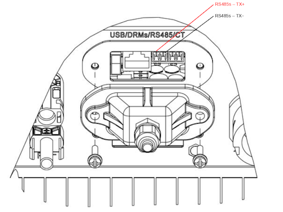
RS485
...TL-G3 & G1 & G2
RS485 Wiring
- For correct RS485 wiring: Follow the guidelines for RS485 wiring.
- If the wiring shown in the table below is incorrect, please let us know.
- There is no general consensus in the industry about the usage of A and B for the RS485 polarity, so it may be counterintuitive and opposite of what you might expect for some devices.
| Device | SmartgridOne Controller model OM1 | SmartgridOne Controller model IG8 | RS485-USB converter | RS485-Ethernet converter |
|---|---|---|---|---|
| RS485s TX+ | RS485 A | RS485_POS | RS485 A | TX+ |
| RS485s TX- | RS485 B | RS485_NEG | RS485 B | TX- |
| N/A | RS GND | GND | Not available | G |
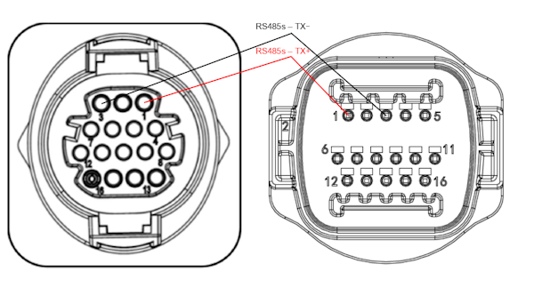
...TLX & TLM
RS485 Wiring
- For correct RS485 wiring: Follow the guidelines for RS485 wiring.
- If the wiring shown in the table below is incorrect, please let us know.
- There is no general consensus in the industry about the usage of A and B for the RS485 polarity, so it may be counterintuitive and opposite of what you might expect for some devices.
| Device | SmartgridOne Controller model OM1 | SmartgridOne Controller model IG8 | RS485-USB converter | RS485-Ethernet converter |
|---|---|---|---|---|
| RS485s TX+ (pin 1) | RS485 A | RS485_POS | RS485 A | TX+ |
| RS485s TX- (pin 3) | RS485 B | RS485_NEG | RS485 B | TX- |
| N/A | RS GND | GND | Not available | G |
Configuración
RS485
NOTE: RS485 Device Addresses
- You MUST give each device on the RS485 bus a unique address. Check the manual of the device on how to do this.
- Use lower addresses first (1, 2, ...) because the SmartgridOne Controller will find them faster!
- For each device, it is generally recommended to stick with the factory default baud rate, parity, and stop bits. The SmartgridOne Controller will scan on those first.
El control externo del inversor debe activarse en el menú de configuración del inversor a través de la pantalla LCD.
- Presione brevemente el botón abajo.
- Verá "1. Ingrese a la configuración", mantenga presionado el botón abajo durante 2 segundos para ingresar a la configuración.
- Pase por la configuración hasta que vea:
- Dirección Modbus o
- Establecer ComProtocol
- Mantenga presionado el botón abajo durante 2 segundos para establecer la dirección.
- Establezca la dirección al valor deseado.